Roger Caffin
There are many references here to my articles and the Forum at Backpacking Light. I am the Senior Editor for Technology there. You will need to be a financial member to read the articles.
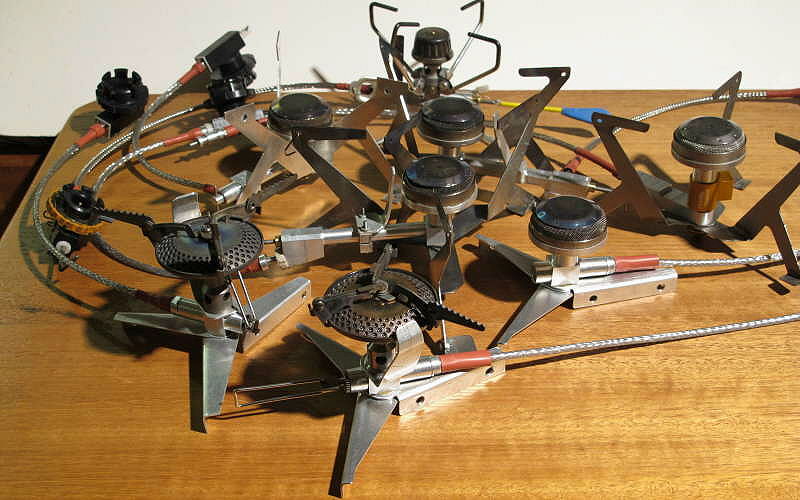
A range of experimental stoves - they all worked
Dissatisfied with what was commercially available at the time, the author has been working on the design of a lightweight winter canister stove since 2007. (OK, OK, a bit obsessive, but so what?) Several novel features were required of the design, in the interests of versatility, functionality and safety. These features are explained and the evolution is traced, ending up with the current design.
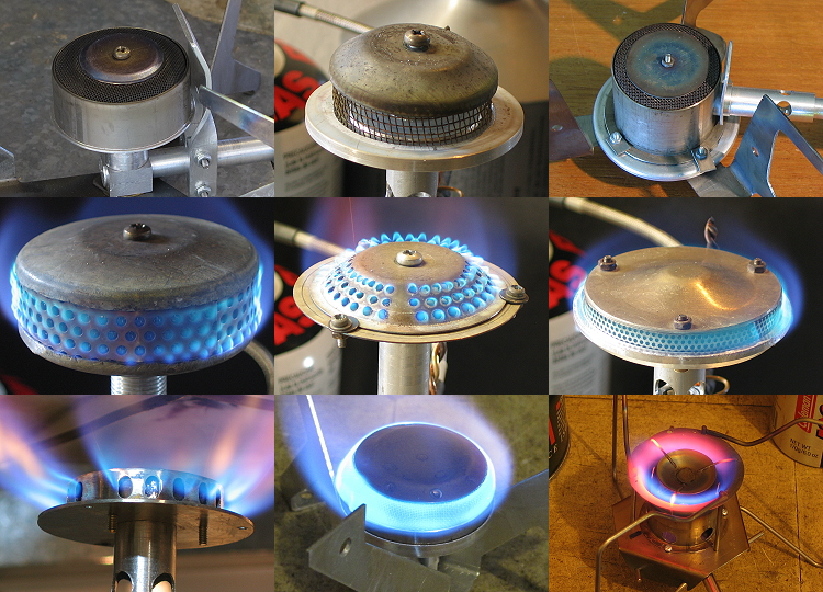
A range of experimental burner heads
Along the way a lot of research was conducted into just how canister stoves work, with special emphasis on the air flow into the mixing column and the way the fuel flows through the burner head. This array is but a fraction of what is in my Reject Bin. Seen in the light of what has been learnt, it is clear many older stoves on the market were designed without enough of this knowledge - and the way they emit carbon monoxide (covered in my lengthy series at BPL on Carbon Monoxide Emissions) is good evidence of that.
Many materials were explored along the way. Brass and steel, the mainstays of the older generation of stoves, have given away to aluminium and titanium. But other materials, such as various plastics, have also been co-opted into the design, very often to reduce the weight. Naturally, fuel and heat compatibility have always been considerations. I have had the fun of a number of 'interesting' failures along the way, including some slightly melted plastic in some commercial stoves.
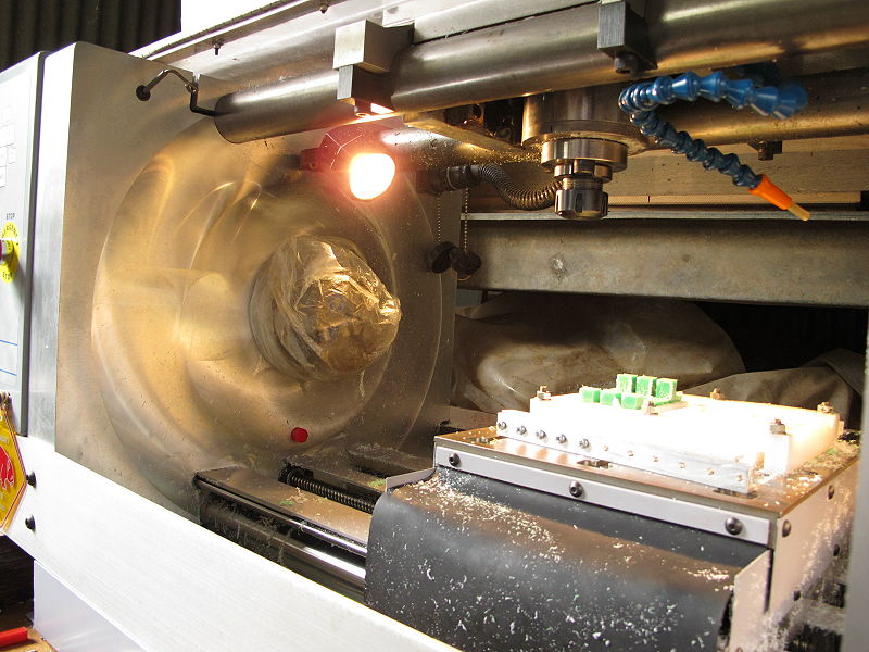
My CNC machine
Finally, to get the precision of machining needed for a reliable design, the author ventured into the fascinating world of CNC machining. While that required a steep learning curve in itself, the use of CNC machining means that designs could be refined in a reliable manner over generations and then reproduced at will, at least to a limited extent.
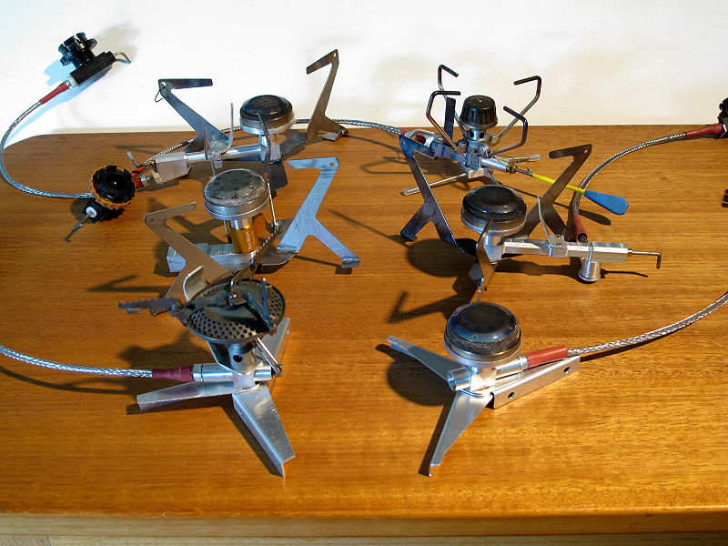
Selected better experimental stoves
Space prevents this series from a detailed examination of the virtues and faults of every model designed, made and tested. This is probably just as well - otherwise it could be too close to the dreaded ordeal of amateur holiday snaps. In case you are wondering, every stove in this photo has significant differences from the rest. Some readers may even recognise the unit at the top right from an article published some time ago: it was an early venture in this direction, and the start of a long road. Evolving the design has been a lot of fun(?). But it may be worth admitting that not everything outlined in this article was understood in total clarity at the start: it has been a long learning exercise! I will add that while I have been learning, it is clear that one or two other designers at one or two Asian factories have been very active in Stove Development. With regret I have to say I have not seen this degree of learning from the traditional Western companies: they are falling badly behind.
In this first part we will explore what I wanted to achieve, the major components of the stove-to-be, and a couple of significant technical decisions. In the subsequent parts we will go into technical details for all the bits and pieces and see what I ended up with.
The starting point for the saga is what I wanted in my stove: the 'required features'.
Use of a liquid feed out of an inverted canister means the remaining fuel in the canister does not plummet in temperature due to evaporation as fuel is used. This is reasonably well-known to most experienced users of canister stoves and is well documented in my article at BPL on The Effect of Cold on Canisters, and is the main rational for the remote-canister liquid-feed winter stove.
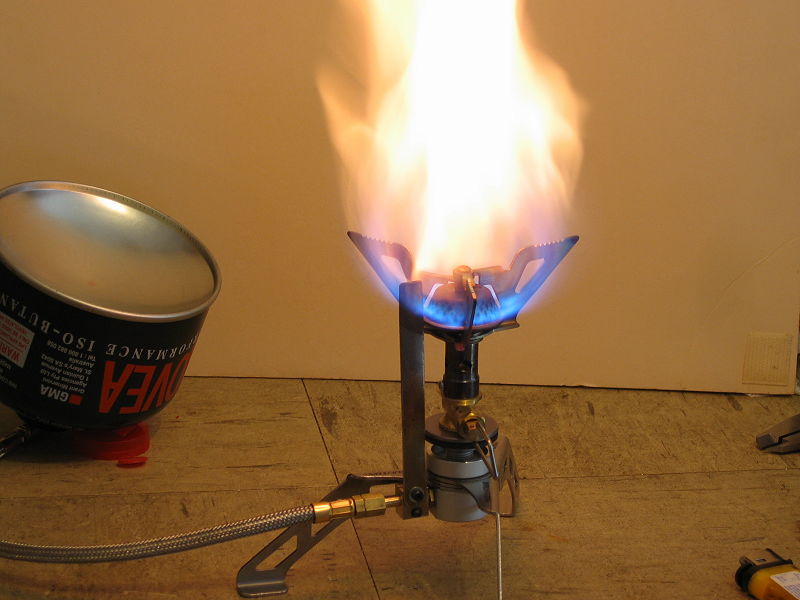
A flare-up due to unvaporised liquid fuel coming out the jet
However, the fuel must be vaporised before it reaches the jet, for several reasons. The most obvious one is that spitting liquid fuel out of the jet produces flare-ups, fireballs, and threatens to burn the place down. Yes, this is actually a posed photo using that Brunton Stove Stand shown above, and not something which normally happens to me. A less-obvious reason is that liquid fuel itself does not burn: it must turn into a vapour first, so it can combine, molecule by molecule (and atom by atom), with the oxygen atoms in the air. Turning the liquid fuel into a vapour is however quite simple: just add some heat. Simple, in principle.
Allied to the need to vaporise the fuel before it comes out the jet is the need to throttle the flow, so one can simmer gently as well as melt snow. In the past almost every liquid fuel stove made has done this by throttling the flow of the liquid fuel, but this presents problems. Since liquid fuels such as butane and white gas expand by a factor of about 250x when they turn into a gas, it is obvious that the amount of liquid fuel going through the control valve has to be very small. And that means the cross-section through the valve has to be very tiny, making it easy for dirt to block the flow and making it hard to get any fine control over the flow. More than one person has made the comment about the MSR Simmerlite stove that simmering is not something it can do very easily. The far greater viscosity of liquids over gases does mitigate this a bit of course.
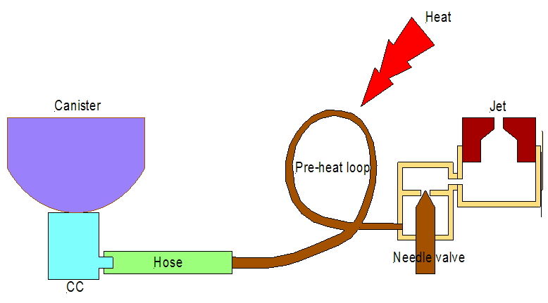
The basic idea for smooth control: valve the gas flow after the vaporisation
The solution is obvious when you think about it: valve the gas flow instead of the liquid flow. That is, put the control valve after the part of the fuel system where the liquid turns into gas. In the very stylised and rough sketch here, the inverted canister sits on top of the Canister Connector (CC) and feeds liquid fuel through the Hose to the 'pre-heat loop', where the heat coming in turns it into a gas. Yes, that is a very rough drawing of a preheat loop, but it will suffice. Then the gas goes through the valve to the jet. Like this you get nice smooth flame control. But almost every commercial remote canister stove puts the control valve back at the canister, the easy, obvious and cheap place to put it. It's just not the right place. Clearly, some departure from conventional thinking is required here to get what I wanted.
No-one wants a fireball when they are cooking. I exempt users of the MSR XGK stove: the instructions do actually state that 'a brief soccer ball size flame is normal'. I have seen the scars on benches in various huts and on picnic tables, although some of those may be from alcohol stoves - maybe. But there is a problem here in the fine details. If the control valve is at the stove end of the hose, then there will be liquid fuel in the hose when the valve at the stove is shut off. When the hose is disconnected from the canister, that liquid fuel can spray out backwards into the air. If there is another stove nearby when this happens, or any flame at all - kaboom. Because of the 'reservoir' of fuel in the hose, under normal circumstances there is a long delay between turning the valve off and the flame going out, which can present also problems.

Basic Lindal connector (uncrimped samples from factory)
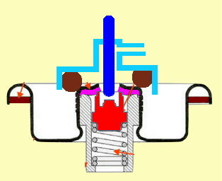
A Safety problem exists even with upright canister stoves equipped with the Lindahl valve. Many users will have experienced that slight hiss you can get when attaching and detaching an upright stove from a canister. That hiss means that the pin (solid blue line, right hand diagram) which depresses the Lindal valve plug (shaded red bit under the blue pin) is opening the valve a shade before the big O-ring (brown circles outside the valve spigot) seals the connection. The standard solution here is to do the attaching and detaching fast, so that very little gas escapes. At least what you get out is normally a gas, not a liquid, provided you hold the canister upright.
Why does this happen? There are two reasons. The first is that there is no real 'standard' for the design and length of the actuating pin, so everyone does it slightly differently. Yes, brand X stove may mate cleanly (without hiss) with brand X canister, but that does not mean brand Y canister is going to. The second is more complex. The Lindal valve screw-thread insert for all canisters (with the possible exception of some Chinese brands) comes from the Lindal factory. They should all be the same out of the factory (and probably are), but they aren't the same when they get to you. The company which assembles (and fills) the canister uses it's own crimping machine, and each machine does the crimp slightly differently. A change in crimping machine meant the Coleman Powermax canister changed the shape of the central nipple by a whole millimetre at one stage.

The (blue) valve actuation pin pushing on the (red) Lindal valve
A solution to this problem of leakage is to make the valve at the canister into a simple safety on/off valve, not the main control valve. Ideally, this safety valve would never be actuated until the O-ring seal (brown circles) has been made and gas cannot leak out. Once the O-ring seal has been made so gas cannot escape into the atmosphere, then (and only then) the blue push rod is pushed downwards to open the actual (red) valve plug. Only then can the fuel escape from the canister and flow out via the outlet pipe (light blue). The difference between this and a typical stove is that here the blue pin is not fixed in position: it can move up and down. Opening the Lindal valve is now quite separate from sealing the connector to the canister.
When disconnecting the stove from the canister you first turn off the safety valve, or raise the blue pin so it no longer depresses the red valve, then you let all the remaining fuel in the hose get used up (burnt) at the stove, and only then do you disconnect the stove from the canister. That way there are no gas leaks at all. This seemed like an fundamental (safety) requirement, and I wanted it.
Hoses: stiff, stiff, and flexible
A secondary safety consideration is the hose itself. With some older stoves you could use the hose as the handle of a battle-axe, it's that thick and stiff and clumsy. (Allegations that the XGK can be used to pound in tent stakes are unverified.) If the stove weighs a ton that may not matter, but with a very light stove you could find the stove held up in the air by such a hose. You need a much lighter hose for a light weight stove. I believe there is a reason why the hose on those older and heavier stoves is like that: the designer (or the factory) just used stock 1/4" reinforced fuel line designed for racing cars. Compatible with most fuels, robust, cheap and not inclined to flap around at 200 mph; just not really suitable for a light-weight stove though. Thinner, lighter and more flexible is possible, as shown at the right.
Sometimes you find that the hose has a bit of a curve in it. That may be due to how the bulk hose was stored in the factory once it was made, or how the stove was packed away in your pot for months on end. Anyhow, in keeping with the prior comments, one needs to be able to rotate the hose with respect to both the stove and the canister to get the curve lined up in a convenient direction. Most older model stoves did not do this (to the user's frustration), although the latest generation do have rotating couplings at one or both ends. The rotation may be a little tight, but that's quite adequate. Such a rotation at both ends was a requirement, even with the lighter tubing.

Pot supports: long and flimsy vs short and solid
Criticism have been made of the pot supports on some stoves. In some cases the pot support is just too flimsy for safety: both the MSR Pocket Rocket and the Primus Micron Ti come to mind here. Those two are shown at the left here, along with some recent Asian stoves with far more robust pot supports at the right. But this detail has two parts to it. The first part is the long length of those thin arms which support the pot: you don't want them that long. The supports on the Pocket Rocket are notorious for bending, and it is easy to see why. With the current generation of smaller titanium stoves (eg the two at the right), the pot supports come from the burner head and are therefore much shorter. I might add that since there is much less area of metal to worry about in those short pot supports, the designers have been able to make them a bit thicker, so they are even stronger. So the worry about collapsing pot supports has subsided.
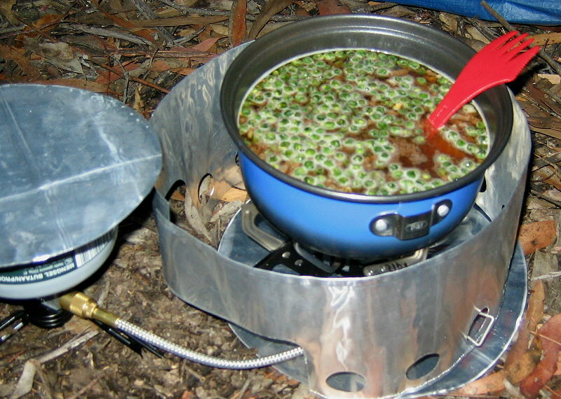
The weight of a large pot of dinner
But there is also the question of the stability of the whole stove: can it collapse sideways under load? What happens when you have a large pot on the stove, full of stew, being stirred? (Hey, we get hungry sometimes!) Both the stove legs and the pot supports must be able to take a bit of a load, and this issue has some sneaky aspects we will return to later. Upright stoves avoid the stove legs problem of course by using the canister as a base, but the pot supports remain an issue. Winter stoves however must also have good legs to hold the stove up.

Lindal connectors, with screw-thread, Campingaz and Powermax
The most common fuel container in America is the screw-thread canister (invented by Epigas, shown on the left), although when I started designing in 2007 the Coleman Powermax canister (shown on the right) was still readily available and is very nicely designed for a liquid feed (with an internal dip-tube). However, when one goes to Europe it very often happens that the only resealable Lindal-valve canister available is a French Campingaz one (shown in the middle), with the French Easy-Clic connection. This is not the same as the screw-thread connection normally seen in America. As an aside: Coleman make screw-thread canisters of course, but they also made the Powermax ones and now own the Campingaz brand as well. Interesting.
The Powermax connector at the right has a sort of hexagonal shape near the base, and this hex shape keys into the Powermax connector. It's a rather complex arrangement, and making a custom connector for it requires that you make a hexagonal broaching tool of the right size, and have a press to drive the broach through the material. It's possible, but slow unless you do it all by moulding. Yes, I made a suitable hex broach which worked fine, but it was hard work with a press.
The common screw-thread connection uses the central spigot as a 'screw', but the thread is atrocious, being barely half there. It tends to rip the thread out of the stove over time, so the stove can no longer connect. That has happened to me in the middle of a long trip, and I had to buy another stove very quickly. It may be cheap and popular, but it is bad engineering. I wanted to avoid the thread.
The Campingaz design does not use the spigot in the middle except as a housing for the valve and as something for the O-ring to seal against. Even then, the design has a secondary seal in it: the red bit shown in the photo under 'Safety'. You can't see it in this photo: it is black neoprene. This rim of neoprene seals against the sides of the valve actuating pin; the gas goes up a hole through the middle of the pin. The stove is clamped to the canister by means of lugs which catch in a groove under and inside the rim of the Lindal valve. This groove is not shown in the (Lindal-supplied) diagram of the Lindal valve in the photo under 'Safety', but is shown below in the section 'Canister Connector'. It is a very reliable and effective means of anchoring the stove to the canister, and is very popular in Europe. But that means that if Campingaz is all you can find in a shop when you need to resupply in some little town in the middle of Europe, you have to suddenly buy a new Campingaz stove as well. They are not expensive, but they are rather heavy and primitive things in comparison. Anyhow, there are no Campingaz winter stoves available: they are all solely for upright summer use (which is a bit wierd).
Some people still have a large supply of the very fine Coleman PowerMax canisters. While we would never recommend you do it, I understand some people even go so far as to refill the empties, just for winter use, because they are so nice and really functional. Compatibility with all three styles of connector would be very nice, and this became a requirement.
While it is great fun making one or two stoves for personal use, a goal was to be able to make a number of these stoves, all quite identical, so they could perhaps be sold. Hey, everyone needs a cool new stove, right?
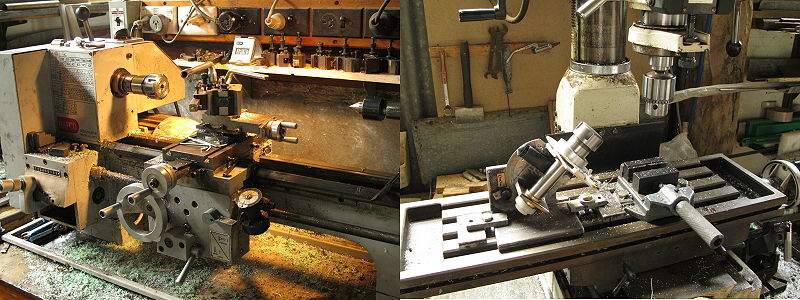
Manual lathe and manual mill
I did some early manufacturing with a manual mill and a manual lathe, but it proved too easy to make every unit unique: just slightly different in some dimensions. And making parts by hand to reasonable tolerances turned out to be very slow, even after the first couple of dozen models were made and abandoned. OK, I don't have a lifetime's experience as a toolmaker. (I just learnt from two very good ones.) I needed to change how it was done - which is in fact the history of production engineering.
I looked at getting parts injection moulded, but there are two problems there. The first is the cost of the moulds. I refused to use a soft low-temperature plastic such as polyethylene here: many parts have to be either a hard plastic such as Acetal or aluminium. Equally, 1 mm accuracy such as you might get from a MakerBot is simply not good enough. Some parts had to be made to better than 0.05 mm accuracy to be reliable - especially for O-ring seals. After some research I found that each mould would cost between $2,000 and $5,000 to be made for me on a CNC machine. Moulded parts (made in China) would then be quite cheap of course. This might be acceptable if I had an absolutely final and perfect design, but I didn't; I was still in the develoment phase. So any change would need a different set of moulds, made on a CNC machine. You can imagine how the cost goes up.
An added complication is ensuring that the Chinese moulding factory did not promptly go into pirate production for it's own benefit, but the advice there was to use several factories and do the final assembly myself. Possible, but a bit in the distance. I discussed making the moulds myself with a CNC machine, but a friend (who knew more about CNC machining than me and actually had his own CNC machine) suggested I make the first 'few' stoves with the CNC machine instead, and get the design right. This was obviously the right way to go.
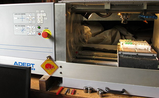
Adept CNC machine: combined mill and lathe
So I bought a small CNC machining centre. It has a full 3-axis CNC mill with an option for a 4th axis (a rotating bed), and it also has a CNC lathe which I have fitted up as a partial Swiss design. I also spent some time getting it going and learning how to program it, but that's a different (and rather long) story. I will simply say that has been lots of fun, with a few anguished moments along the way. Broken milling cutters are not unknown in the trade, and they cost money. A common saying among CNC users is that a CNC machine allows you to make many identical, very accurate parts at high speed, but all equally wrong. This is true. But what did come out of the CNC experience was a slight change in design thinking, so that as much of the stove as possible could be made in multiple units in parallel on the CNC. Once you get into making ten at a time, things really start humming. Injection mouldings can come later. Hopefully, the design will be final by that stage.
In Part 2 we will get down to some hard details; in Part 3 we will look at the final result.