Roger Caffin
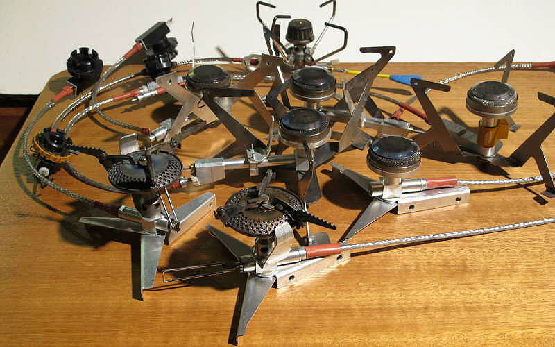
A range of experimental stoves - they all worked
Disatisfied with what was commercially available at the time, the author has been working on the design of a lightweight winter canister stove since 2007. (OK, OK, a bit obsessive, but so what?) Several novel features were required of the design, in the interests of versatility, functionality and safety. These features are explained in Part 1. In this Part 2 we go into finer technical details about how the features might be implemented: all the choices which were possible. In Part 3 the final stove will be presented.
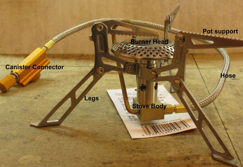
Five main parts to a remote canister stove
We will break the stove up into five major sections, illustrated here with a recent commercial (Fire Maple FMS-118) stove. The sections are the canister connector with on/off valve (a flow control needle valve here), the hose with its connections, the stove body with the heat exchanger and control valve (which is not present here at all), and the burner column and burner head. Some of these will get a light treatment, while others will get more detail. Finally, the fifth component is the combination of pot support and stove legs. This tends to be complex and depends on other factors.
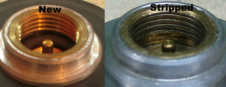
What a screw-thread connector should look like, and what can happen
I have explained why I wanted a 'universal' canister connector. I will add to that requirement my experience with a Snow Peak GST-100 stove in France one year. The steel screw-threads on the canisters are very poorly formed: they represent no more than half a thread at the best. I am sure the steel thread will last far longer than needed, but what about the brass thread on the base of the stove? Well, against steel, brass wears away. Half way through the trip I found that the thread on the stove had stripped off to the point where I could no longer get the stove to stay on the canister. The thread on the left is basically a new thread; the thread on the right is how my stove ended up. I am definitely not going to blame the stove for this: it is absolutely the fault of the poorly formed thread used on the canister, plus the many years I had been using the stove. From an engineering perspective, the screw-thread connection is a crappy design. I wanted a more reliable and longer-life connection.
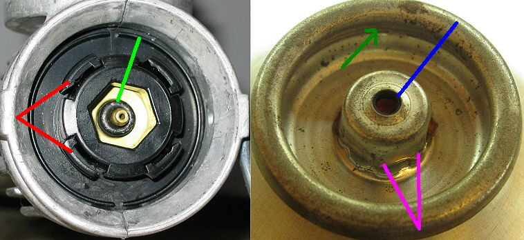
Details of the complex Powermax connector
The Powermax connector does not use a screw thread. It uses lugs under the rim of the Lindal valve to anchor the connector: two lugs are pointed to by the red lines. They lock into (under) the overhang in the Lindal valve pointed to by the dark green arrow. The rotation for this is driven by the hex shape on the spigot, which keys into the Powermax connector. You poke the canister into the connector, push hard against the O-ring on the actuating pin, and twist. The hex keying turns the central bit of the black plastic connector so that the lugs expand outwards under the rim. The connection is very solid, when it works properly. The tiny O-ring around the valve pin actuator, pointed to by the light green line, seals against the top of the spigot on the canister. The gas goes up the tiny hole visible in the middle of the actuating pin. In engineering terms, it works but is rather complex.
Making a custom connector for the Powermax canister requires that you make a hexagonal broaching tool of the right size, and have a press to drive the broach through the material. It's possible, but slow unless you do it all by moulding. Yes, I made a suitable hex broach, but it was hard work with a press. In addition, the complex molding used for this connection was more than I could make in my workshop, so while I liked the lug anchor, it was not a viable solution by itself.
It is worth noting that all this is conditional on 'when it works properly'. Lots of lab testing by Coleman showed the connection was very reliable, but Coleman kept getting reports that users found it hard to make it work in the field, sometime impossible. Curiously, the same users often reported that the stove worked just fine when they got back home. Coleman could not make any sense out of the reports and the matter rested there for a few years. Successful users loved the stove, but others were just frustrated.
I had the same problem in the field, but I spent some time exploring the problem. The usual suggestion from experienced users was to push the canister into the connector a bit harder. I found this worked. Now, why should it be harder to get the canister into the connector in the field? Realisation dawned: the tiny rubber O-ring seal on the connector (light green line) was getting so hard in the cold that it could not be compressed enough. Of course, when you got home and into the warmth, this problem disappeared. I explained this to the appropriate Coleman manager, who took the information back to the lab. I gather they had done most of their lab testing at a comfortable room temperature! Coleman promptly revised the centre of the connector just slightly, so they could stack 2 O-rings on the valve pin. This allowed a just a little easier compression in the cold, and the problem was solved.

How the reliable Campingaz connector works
The Easy-Clic connection shown in the middle is used on the French Campingaz stoves and canisters. It was developed by French engineers in reaction to the crappy screw-thread connection developed by the British Epigas company (now owned by the Universal Trading Co of either Japan or China). English/French rivalry, anyone? In fact it is simpler and far more reliable then the other two forms, and it's a pity it did not really succeed outside of Europe. Basically, the idea is that a 'spider' (pale blue, left picture) of shaped fingers are pushed into the Lindal valve and then locked in place under the internal rim of the Lindal valve by a solid core (red). Yes, the finger idea is similar to the lugs in the Powermax connector (and preceded the development of the Powermax too). Later on the conventional sealing O-ring (shown roughly by the green circles) is pressed down onto the Lindal valve head as the (red) locking core is screwed further down.
Some adjustment of fit is available here as the mechanical locking function is reasonably separated from the sealing function. That is, the red cylinder locks the blue fingers into the Lindal valve before the O-ring makes contact, but the red cylinder can keep screwing downwards for some distance. In other words, one can first get the locking function working, then continue screwing the main body in until the O-ring seal is snug. This makes it adaptable to slightly different-sized canisters and Lindal valves. Oh yes, variations in canister shape happens. However, there is no disconnect between 'sealing' and 'actuating' (via the blue pin shown at the right) in this design.
Life is never entirely simple however. It turned out that the exact dimensions of the Lindal valve insert varies between connection types (screw-thread, Campingaz, PowerMax), and even varies slightly between canister-making and gas-filling factories. Not to mention that the shape of the little valve plug inside the spigot can vary widely - that's the red bit in the cross-sections shown at the right'. The depth to this valve plug inside the Lindal spigot also varies between brands, much to my annoyance.

Variations in the Powermax canister nipples
For that matter, at one stage Coleman made a huge (relatively speaking) change of over 1 mm in the way the central spigot sticks up from the rim of the Lindal valve, as shown here. Yes, they are both Coleman Powermax canisters. Actually, I don't think that the Coleman company themselves made the change: I believe it happened 'accidentally' when the canister-supplier changed the canister crimping machine, or maybe when Coleman changed gas-filling factories. I challenged them on this but they did not seem to be worried - or did not understand the significance. For those with the Coleman Xtreme stove, I can say that both versions work fine.
So the problem became one of finding out whether a single canister connector and actuating pin length could be used across all three canister systems.
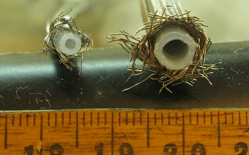
Thin (light & flexible) hose and thick (stiff & bulky)hose
The semi-rigid 1/4" race-car fuel line used on older stoves (as shown on the right) was simply not an option, so a new hose of smaller diameter had to be found. The material has to be fuel-proof and able to take a high temperature - at least at the stove end. It also has to be fairly flexible. A target outside diameter of 3.2 mm (1/8") would be nice - based partly on what was known to be available. The hose on the left shows a suitable target size.
While there are some nice flexible plastic hoses designed for use as fuel lines on small IC engines, most of them won't take the high temperatures which may be encountered in a stove. They soften around 100 C, which is just not acceptable for safety. However, three plastics are suitable and commercially available: PTFE (Teflon), PFA and FEP. (In fact all three are chemically very similar materials.) These plastics can take both very high temperatures and very low temperatures, they are fuel-proof and strong, and the available hose sizes can easily handle the high pressures involved as well. In addition, they are available from a number of manufacturers, so the price is at least slightly competitive. Actual temperature rating for PFA tubing for example is -184 C to +260 C (that is not a typo!).
However, while suitable tubing is available, the small diameters needed do not normally come wrapped in stainless steel braid (although some large diameters do). Before going any further here, we must ask why (whether) the braid is needed. It turns out that on racing cars the braid is there to handle external abrasion - to handle the hose rubbing against something while the car is doing 200 mph around a track. The fuel line itself has no need of the braid for strength. So historically, small stoves have braid on their fuel lines, simply because that was what was available. Well, OK, maybe the braid does offer a small degree of protection against the fireball priming technique.
Nonetheless, the market probably expects a braid cover. It has some advantages in terms of both strength along the hose, burst strength of the hose, and, well, defense against abuse. The problem is finding suitable small tubing with stainless steel braid, or suitable tubing and suitable braid.

Typical barbed connector for a larger hose
A large-bore hose can be fixed over a metal spigot (often known as a barbed fitting and illustrated here), and the result may be strong enough. Common garden irrigation systems and garden hose tap fittings do this, as do a lot of other hoses with a bore of over 10 mm. However, reduce the dimensions to suit the little hose to be used on the stove and the result becomes a bit weak. In this case the OD of the hose is just over 3 mm (1/8") and the ID of the hose is under 2.0 mm (1/16"): we are talking about the size of a medium-sized hypodermic needle (well, for horses anyhow) here. And the wall thickness for the hose is only about 0.8 mm (1/32"). That combination is just not strong enough for field use, and the consequences of a break in a fuel line are 'never good'. Trust me.
The alternate approach puts the hose up the inside of the connector as shown conceptually below on the left, and the hose is expanded ever so slightly at the end to a gas-tight seal. This works for sealing the gas and supporting the hose, but leaves open the question of whether the slippery plastic hose could be accidentally pulled out of the connector. These hose plastics are just a bit slippery, and you don't want fuel spraying everywhere. In case you are wondering, yes, the hose can be pulled out of the hole, albeit with some force.
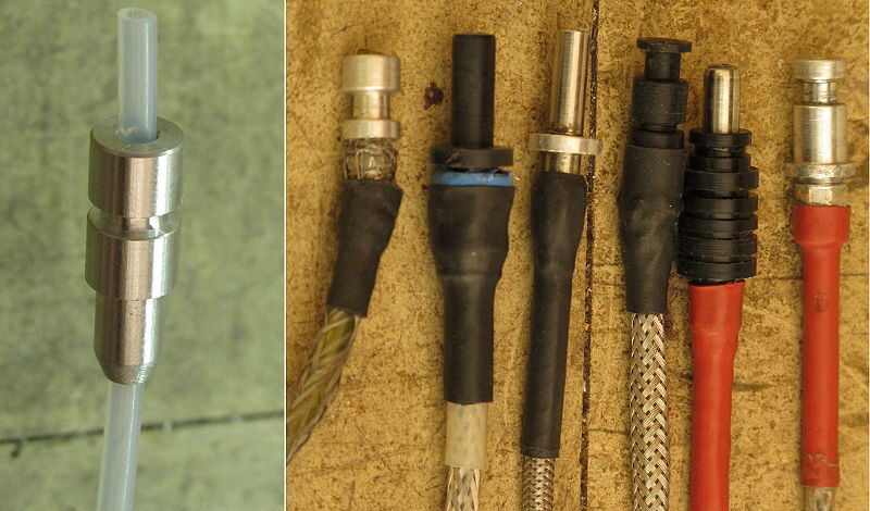
A range of experimental hose connectors
On the right of this photo we have a range of connector designs I experimented with, using nylon, stainless steel tubing and aluminium alloy. The stainless steel option (2nd and 4th from the right) sounds heavy, but it was not really as the hard stainless tubing used was quite thin-wall. The nylon option was strong enough in itself for the PFA tubing, but it was not strong enough to anchor the braid. In addition there was some doubt about how well it would work if it got to, say, 100 C. Safety remains a very high priority when playing with a canister full of fuel.
The connector at the left shows what I ended up with: a simple 8.0 mm rod with a hole up the middle. There is a smaller bit at the end for crimping the braid onto, and there is an O-ring groove in the middle for sealing. Such a simple design does conceal a few refinements of course. The principle one worrth noting is the quite tight fit of the connector in the socket: too much wobble is dangerous.
To seal the hose connector into the sockets in the parts at each end it is normal to use O-rings, although some commercial stoves have used a flared brass tube pressed hard against an end of the right shape in the past. The brass connection works reliably if the connection is tight enough, but it does not permit a rotating connection. As mentioned in Part 1, rotation of the other parts of the stove at either end around the hose is very useful and is a requirement. The right diameter for everything lets rotation happen without leaks.
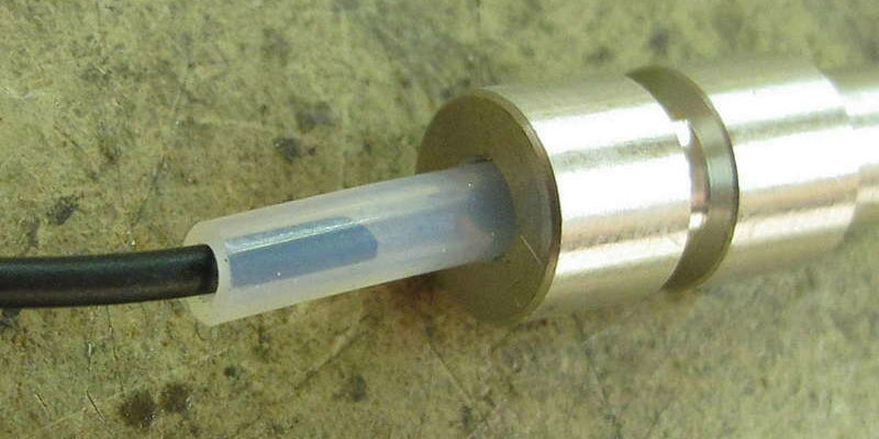
Filling up the bore of a fuel hose
Of course the hole down the middle of the hose can hold a lot of liquid fuel, and this can take some time to burn off after the on/off valve has been shut. The normal thing to do here is to partly fill the bore of the tube with a filler cord of some sort, as shown here with some black nitrile cord from an O-ring kit. There is in fact a delicate balancing act here. If the filler cord is too thin then a lot of fuel is left in the bore, which is annoying. But if the filler cord is too big there may be too much restriction on the flow of fuel down the hose - and remember there is a fair length of this bore to consider. The addded complication is that whatever is used has to be fuel-resistent. The diameter of the filler cord needs to be fine-tuned.
Some stove companies have passed this filler cord off as a cleaning wire - for instance MSR use a bit of stainlesss steel cable in their stove and call it that. I guess if the auto gas fuel used contains lots of nasty additives it might be necessary to clean the hose out sometimes.
This could become a very long section, so we will skip very lightly over the many, many designs tested, only some of which are shown in the lead photo. (For instance, none of the vortex burners I have built are shown there.) Critical to the design of the stove body are several factors: burner type, valve arrangement and thermal feedback method. They interact. We will skip quickly towards the end lest I become boring. The section on burner type will help explain why. The next section turned out to be more important than I had expected.
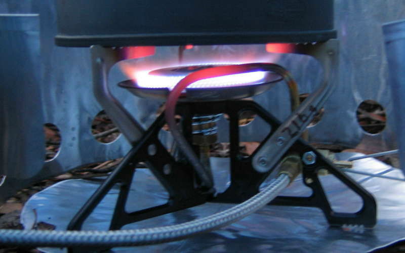
A glowing preheat tube - but is bright red really necessary?
Conventional stove design has a pre-heat tube going through the flame. Why is this so? It derives from the need to boil kerosene into a vapour in the first 'miniature' stoves developed - as originally made by Primus a long time ago. Kerosene boils, so to speak, anywhere between 150 C and 300 C, depending on just what is in it. Yes, just like auto gas (petrol) and diesel, the composition of 'kerosene' can be rather variable. Ask any diesel owner about the difference between summer and winter diesel fuels. So clearly a lot of heat is required, and so the pre-heat tube goes through the flames, where it can reach a glowing red 500 - 600 C. That's great for kerosene.
But butane boils at 0 C and propane at -42 C. Why on earth should a canister stove need a glowing red-hot pre-heat tube designed for kerosene? Well, it seems to the author that the most designers of remote-canister stoves never really thought about this; they just did the same as before, all the way back to very early kero stoves. Logically speaking, as long as the fuel reaches about 10 C before it gets to the jet it will be a gas. If it gets that warm before it reaches the valve adjacent to the jet, that is even better as you are now valving gas, not liquid. But does it need to get to red heat? Looking at this another way - water boils at 100 C; can you imagine how fast it will vaporise if raised suddenly to 10 degrees above this - to 110 C? Whoosh! Have the 'designers' even thought about this? I suspect not.
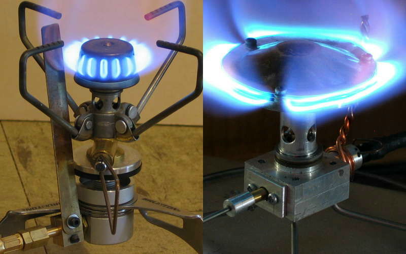
Alternate 'heat shunt' approaches to preheating, with copper strip and copper wire
This was discussed in our article on the Brunton Stove Stand, published in 2008. In that article a 'heat shunt' was used to bring heat down from the flame to the region of the hose connector and control valve. Provided this is done correctly, it works just fine. According to Christopher Witter, a simple bit of heavy copper wire actually suffices, in place of my nicely engineered fin. I tested this with one of my burners, as shown on the right. Yes indeed! But none of the big manufacturers seem to have taken any notice of this. (I will add that there are many ways of doing this wrongly ...)
A hidden feature here (if you can call it that) is that it takes time for enough heat to flow from the heat shunt down to the fuel, and more time to flow right through the fuel. If the fuel passes through the pre-heat region in a thick solid stream this can mean that the outer layers are vaporised but the core of the fuel flow stays cold, and reaches the jet as a liquid. This is not good: fireballs can ensue, or at least lots of spitting. Instead we shaped the fuel into a thin film as it flows, to get maximum heat transfer. It also means that the stove will still need to be 'primed', or at least allowed time to warm up enough, before it can be turned up to full power. There are more complex fine details in the fuel flow of course, but they are details and can be solved.
By now it was fairly clear that I wanted an on/off safety valve at the canister plus a flow-control needle valve at the stove - working on the gas flow. No other light walking stove has this feature. We will look at each valve separately.
The on/off valve at the canister needs to be independent of the connection/sealing function: that's a requirement for safety. This means the actuating pin needs to be movable, unlike most stoves where the actuating pin is fixed in position. That is, it needs to be retractable, or to be able to be pushed down into the valve.
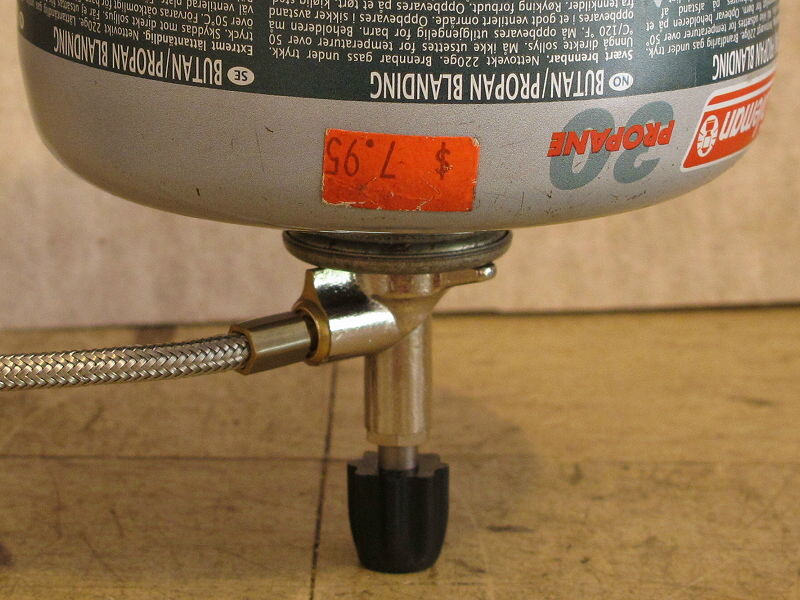
A rather awkward valve arrangement, prone to accidents when in a hurry
The first method tried for this was a simple screw-driven pin: turn the screw and push the pin down into the valve. In fact, this is a reasonable method, except for two things. It places the on/off valve control handle right under the upside canister, as shown here. Primus have used a layout like this on some of their stoves, although the knob drives a conventional needle valve rather than the actuating pin. Anyhow, and I found the arrangement quite awkward to manage. Also, with the pot sticking up in the air like that, it can be a bit slow to turn off when one is in a hurry, and there is the obvious risk of sending the both the stove and the pot full of (boiling) food flying if you are suddenly in a rush. Then you have a burning stove upside down and flying around. Not such a good idea.
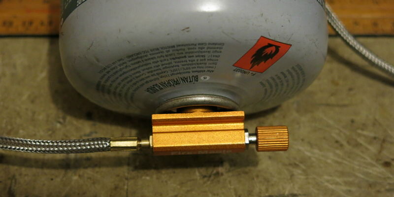
A much more amenable valve arrangement with better access
If a screw thread going straight in is awkward to operate, that meant I needed a control sticking out the side. Many remote-canister stoves have this sort of valve and connector on just a screw-thread, and experience shows it is far more convenient to operate. The one shown here is on a Fire Maple FMS-118 stove. Even when the canister is upside down the valve handle sticks out the side and can be adjusted without moving the canister. This position for the valve handle is much safer. However, all those commercial connectors still have a fixed actuating pin. You can still get a leak while connecting the stove to the canister.
One way to get a movable pin is to have a cam system inside the connector body which drives a short sliding pin. This turned out to be both possible and useful, in that going from on to off is usually just a quarter turn at the most. Well, actually, a cam design normally works over a half turn, but using only half of that rotation is faster and leaves a margin for tolerances and safety.
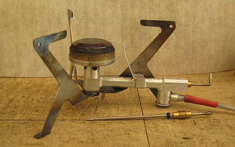
A lovely long Ti wire needle valve - which jammed
A needle valve is used to control the flow of gas to the jet. This aspect was extensively discussed in our article on The Myth of Pressure Regulators. However, practical implementation of a suitable needle valve is another matter. One design which seemed to be very nice (on paper) used a long tube for the gas to vaporise in, with a long titanium needle valve down the centre. The hole or bore around the Ti needle was large enough for a thin film of fuel and was quite long, which was excellent for getting it vaporised. It was a nice design (anything Ti is nice), but it failed in testing. The difference in the coefficients of expansion of aluminium and titanium, combined with the long length, spelt trouble. When a hot stove was shut down by closing the Ti needle valve and cooled off, the aluminium shrank more than the Ti, and the needle valve became jammed. Every time. That wasn't so good. I did consider a long aluminium needle, but aluminium is a bit soft and bendy over that sort of length, and the reliability did not seem adequate. So a short needle valve was needed.

Two directions for gas flow through a needle valve
A fine detail on needle valve design which emerged only slowly was that the direction of fuel flow through the needle valve does matter. It is not immediately obvious why this is so, and it really only applies to remote-canister stoves anyhow. It concerns dirt and blockages. When the fuel flows down the length of the tapered needle valve in the direction of the dark blue arrow, it can jam in the hole. The dirt and wax seems to collect around the needle. Opening the valve up does not seem to help clear any obstruction very well: the gas pressure just jams the dirt in the tiny gap harder. But when the fuel flows against the direction of the needle valve, in the direction of the light green arrow, it seems to clear far more easily - especially if you very briefly open up the valve. Then the gas pressure blows the dirt past the needle valve seat and out of the way.
Is there dirt in canisters? Well, my experience has been that there is little or no dirt or foreign matter in canisters from most filling companies used by Western, Korean or Japanese brands, but I have had really filthy fuel from at least one Chinese filling company (unfortunately co-branded with Primus). It took no more than about 1 minute of operation to block the needle valve and jet on each of several tests runs. As far as I could see, there was a lot of very fine dust in the fuel which had never been filtered out from the raw gas feed at the factory (cheap, cheap.) I guess that if you only use the canister upright the dust mostly stays at the bottom. I returned the two canisters I had bought and got my money back.
Other 'foreign matter' can also be found in some cheap canisters: it seems to be dissolved paraffins. These are just higher-order hydrocarbons from the raw fuel out of the well. They too stay at the bottom of the canister when the canister is upright, so their presence does not matter either. But with an inverted-canister liquid-feed stove the paraffin can collect around the needle valve in some designs, especially if the fuel cools a bit on expansion. Been there, seen that, cleaned it off (see Stove Maintenance for how).
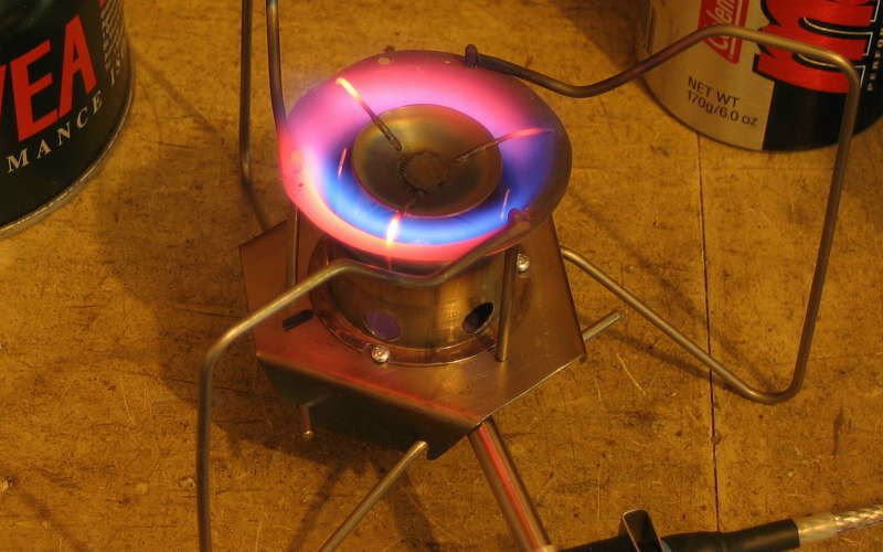
The basic vortex burner design - it works very well
You thought we had already got technical? Oh no, we were only just starting! You see, there are several sort of burner designs possible, and they are really very different. We can break them up into two major classes: quiet pre-mixed burners (often called 'silent' burners) and vortex burners. The latter class are exemplified by the MSR XGK stove, and are distinguished by operating with a very loud noise. The noise is actually inherent in the vortex design: the flow is oscillating at an audible frequency - many thousands of time a second, but chaotically. The result is a lot of white noise, or a roar. The design is quite attractive (as illustrated here) if you don't mind the noise, but some parts of the burner are tricky to make without some heavy gear. Also one needs to be able to reliably spot weld Ti sheet and wire - and while possible it is not easy to do with high repeatability and reliability in a home workshop. A number of Ti models were made, but the concept was eventually abandoned for manufacturing reasons: I did not have the heavy gear needed.
The quiet burner, which may be exemplified by the well-known Snow Peak GST-100, consists of a jet of fuel which entrains air as it goes up a tube, then the fuel/air mix is deflected sideways to come out of holes in the head of the burner and forms a flame. Sounds simple, but in fact the fine details are surprisingly complex. We will be brief.
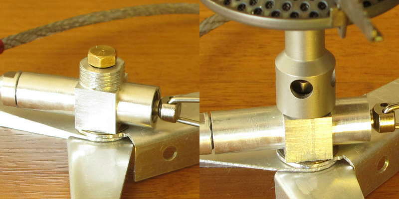
The position of the air inlet holes with respect to the jet
Inspecting the burner tube on most any small upright stove shows the jet sitting in the middle and blowing past a number of air-inlet holes. The speed of the jet past the holes sucks the air in through the holes. Simple. However, get the layout of the jet, the holes and the inside profile of the tube wrong and the whole thing becomes a total mess. At one stage I was able to make an experimental burner (tube) work far better by blocking half the air inlets! It was most illuminating.
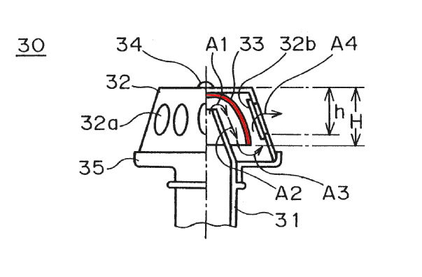
Patented interior design of the Snow Peak GST-100 burner
When the fuel/air mix hits the inside of the burner head it has to deflect sideways. Do this wrong and the stove just won't work: too much back-pressure is created at the top of the burner tube. Snow Peak actually have a US Patent (5,957,683) for the fine details inside the head of the illustrious GST-100 stove. Their patented 'insert' (shown in red) shapes the gas flow, and I can confirm from experimental work that what they reveal in this patent really does work and works well. I will add that the Patent claims do have a serious hole in them which can be exploited, but no matter.
I spent a lot of time on burner design. I lose count of the number of designs tested, but an earlier photo will serve to illustrate the range. I wanted to make my own burner head, and did succeed with several very effective designs, using aluminium, titanium and stainless steel mesh. I had better explain about the mesh here: it goes over the larger opening(s) in the burner head and is essential. In fact, most burners have some sort of mesh at the outlet holes. The idea is that the fine gaps between the wires prevents the flame from burning back inside the burner head. The idea originates with the Davy Safety Lantern (~1815) invented for use in coal mines. If the flame ever does get inside, the burner head gets red hot very quickly and the whole thing can melt down. It can also happen if the flame gets anywhere near the air inlet holes, and some stoves are a bit susceptible to this. One Bu-Lin (Chinese) copy of the Whisperlite did this every time I fired it up! They had made such a 'small' change to the design too, just to make assembly easier. Dangerous stuff, ignorance.
The vortex burner design illustrated in a previous photo has a lot of merit if you don't mind the noise. It worked quite well. However, forming the tapered burner chamber with the machinery I had was difficult, and forming the splash plate sitting on top was very difficult. Well, forming it was easy, but getting it securely attatched to the top of the chamber was difficult without a large stamping press. I would add that one Antarctic expedition a long time ago very nearly came to grief when the splash plate on their early stove burnt out. Without that plate the stove did not work. Fortunately, one member of the party was able to patiently file another splash plate out of some sheet steel they had 'lying around'. I guess he had 'all the time in the world' to do this.
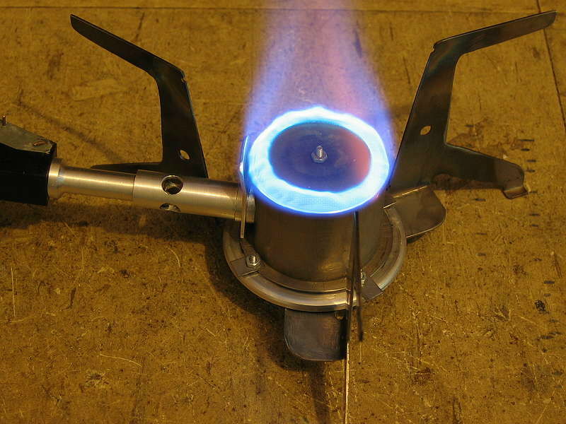
Unsuccessful side injection burner design
I also spent some time exploring the possibility of creating a somewhat different burner, one which (sort of) combined some features of the 'quiet' burner with some features of the vortex burner. The idea was to have side injection of the fuel/air mix into a mixing chamber, with flames out the top. The idea worked quite well, but once again forming the titanium body was hard work with my machinery. It would be easy enough to do with a hot press, but there aren't too many of them around the world.
I will add here that the position of the heat shunt seen in this photo - that strip of aluminium going down from the flame down to the injector, turned out to be totally wrong. It just cannot work in that position. Understanding why it wouldn't work was actually a significant step forward in winter stove design theory, even if it meant abandoning this design.
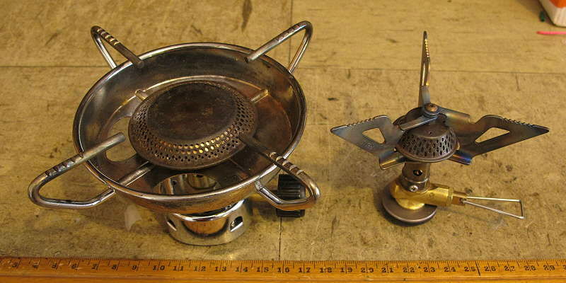
A heavy traditional steel stove and a modern light Ti stove
The very old traditional large steel burner found on many cheap family-camping stoves is actually quite good in design. The gas flows out nicely at low speed, so there is no risk of flame lift-off, and the steel 'windshield' under the burner thoroughly masks the air inlet holes from the flames. It also prevents the radiation from the flames from overheating the canister underneath. The very wide pot supports are more tolerant of novice clumsiness. A pity it is so unavoidably huge compared to a more recent model on the right, and so massively heavy at 310 g. Nonetheless, that stove has been on many day-walks and made many cups of tea and coffee. Nice idea, but ...
One thing some of the more recent burners have in common is the use of a metric fine 12x1 mm thread between the burner tube and the stove base. (But not the Snow Peak GST-100 stove, sadly.) This allows you to swap burners around a bit, provided the air inlet holes are in the right place. I went along with this thread during my development work, and wasn able to test out several commercial burner heads on the same stove base as a result. The second photo under 'Burner design' illustrates the thread.
An slowly dawning advantage of thinking in this direction was that some modern upright stoves can be got from China in bulk at a reasonable price, if you can get the factory to talk to you. With the right selection, the result can be very light. Also, by buying a commercial stove for the burner head, one usually gets the valve and the jet (with its tiny hole) thrown in without doing any extra machining. Yes, I can make jets with their tiny 0.28 - 0.32 mm holes on a (slow) production basis, but it still takes time. For those interested in the machining technology: the tiny drills are from Switzerland, they are very expensive, and they break very easily. Don't try this with a hand-held pistol drill, nor with a lathe headstock which is ever so slightly off-centre (most are). Being 0.05 mm off-centre does not matter with a 6 mm drill bit, but a 0.3 mm drill bit is quite another matter.
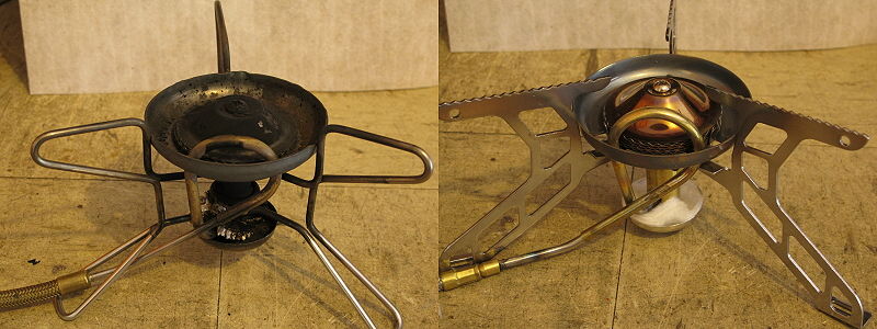
Whisperlite stove and very dangerous clone
One can add a lot of weight to a stove with the wrong design and the wrong materials here. Some stoves seem to have absolutely massive legs. Granted, some would appear to clones of well-known American models: which one here is the Whisperlite International and which is a Asian clone with heavy steel legs - possibly made by the same factory which made the Whisperlite? (Hint: check for soot from use.)
And purely as an aside, the copy shown here was prone to serious back-ignition after a minutes or so. That is, the flame went inside the burner head, which latter then glowed very bright red! Yes, the reason was obvious - after the event. Just a small innocuous change to the original design ...
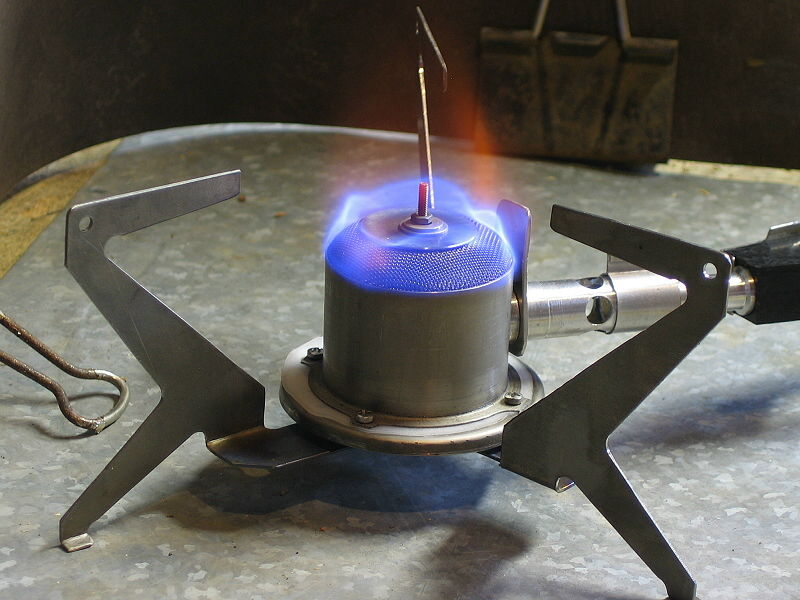
Titanium stove legs
I have experimented with many designs of combined pot support / stove legs, made of titanium and aluminium. To my initial surprise, I found that the extra stiffness of titanium over aluminium was not all that effective. Many of the Ti legs I made were still quite wobbly. It took me a little while to work out why that was so.
Actually making the Ti stove legs was also a bit tricky. Cutting out complex shapes can be done with a waterjet or a laser, but the cost is a problem. I cut these on the CNC mill: maching Ti is different from machining steel or aluminium. Getting the 90 degree bends in hard 6Al-4V alloy is also hard: you need a 'hot press' as you can't bend the alloy cold without it cracking. I had to develop a hot press for this.
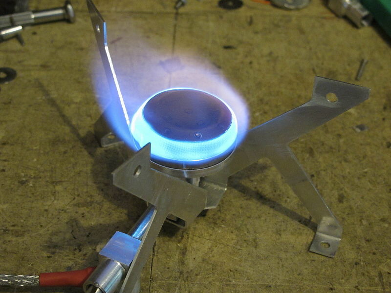
Aluminium stove legs
What turned out to be more effective was increasing the thickness of the leg material. At this point I realised that making the same design out of 0.6 mm thick Ti and 1.2 mm thick Al gave close to the same final weight, but the double thickness of the aluminium actually made the Al legs a bit stiffer! Not obvious at all, until you sit down with the equations for beam stiffness. There are some power laws in there which really scale the effect of the thickness of the material right up. Machining the aluminium sheet is only slightly easier: it can clog up the cutter and break it if you are not careful. That gets expensive very quickly.
But surely aluminium pot supports would just melt - like the fins on a Jetboil Sol pot sometimes do? Well, it turns out that this may be true if the pot supports are really thin: you can't get enough heat flow away from the flame fast enough. But when the metal is, say 1.2 mm thick, and there is only the tip of the leg in the flame, the heat flow away from the flame is good enough that the metal does not get anywhere near melting.

Red hot (steel) pot supports and surrounds
Mind you, the smart designer does not put an aluminium pot support right into the flame. Rather, he puts the put support as far out as possible. As you can see here on the left, the (steel) pot support on a Fyrestorm glows red hot near the middle of the flame, but out near the edge of the pot - no worries. The Snow Peak GS-200 (white gas) stove seems to deliberately put its steel baffle into the flame, so it glows bright red, but the wire supports just a little further out don't glow. So it all depends on exactly how far into the flame the supports go. That said, I do put the 1.2 mm thick aluminium heat shunt on my stove (as explained in the Brunton Stove Stand article) into the just the edge of the flame to get lots of heat into it, but that's only for a few millimetres. The heat gets pulled away quite quickly, down to the stove body.
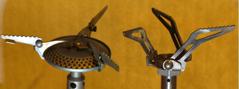
Modern pot supports: short thick titanium
Of course, if a commercial burner head with integrated pot supports is used, as illustrated here, you don't need to make up a pot support. What's more, if you pick a good (modern) stove the pot supports come from the region of the burner head rather than down near the bottom of the stove, so the amount of material required is far less. Since there is so much less material used, one can afford to use nice thick titanium, between 1.0 and 1.5 mm thick in fact. That's really solid.
Even if the pot supports come with the burner head, you still need some way of stabilising the whole stove. Several interesting discoveries were made here (which is why you must do lots of field testing!
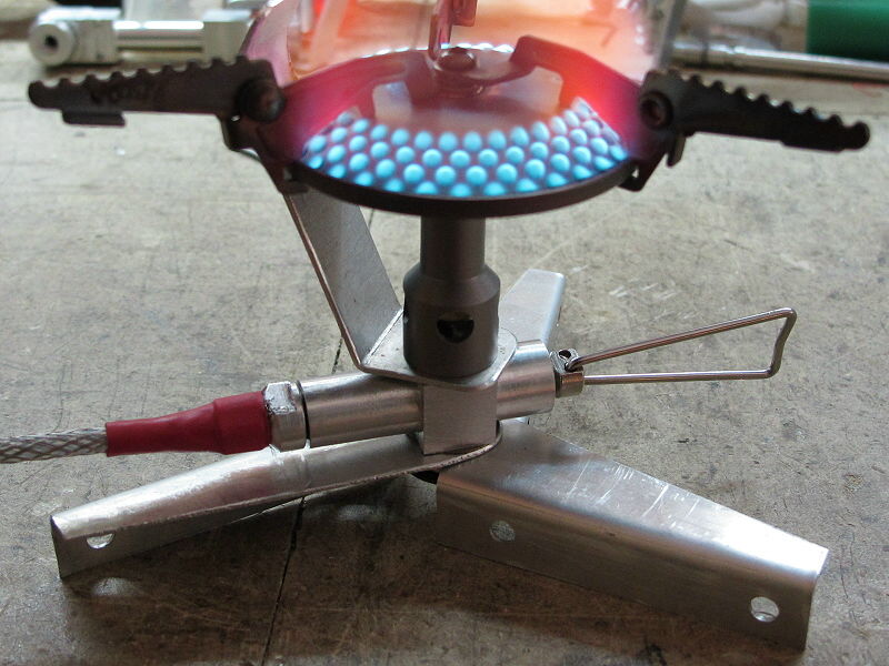
Stove and flames and valve handle too low to the ground
The first was that having the stove too close to the ground was definitely not good, and there are two reasons why this is so. The first is that you obviously don't want the flames too close to any flammable material under the stove: dead grass, leaves, table tops, etc. The second was discovered the experiential way. You don't want the stove too close to the ground because then you can't get to the control valve without burning your hand. You need some clearance! OK, all I lost was a few hairs off the back of my hand. That's experience.
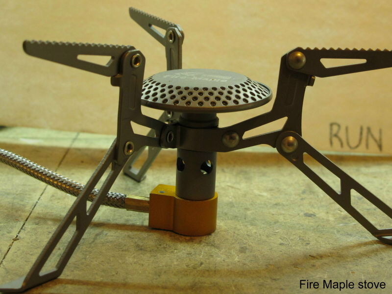
Central stove support to take the bulk of the weight
The second discovery was that the pot supports serve two functions, not one. Yes, they do stabilise the stove so it does not tip over, and for this they should spread out fairly wide. Close to the pot diameter seems to be a good rule of thumb here. But I found that a big factor in stove and pot stability is actually vertical movement. If the legs flex so the pot goes up and down, stability is threatened. If one leg flexes under load and then springs back - 'oops' becomes a possibility. But support the main weight of the pot right under the stove body so there is far less flexing going on, and stability improves markedly. For this reason some very recent stoves have had the stove base pretty much touching the surface the stove is sitting on, and this does work - provided the stove body does not get too hot of course. This became a desirable feature.
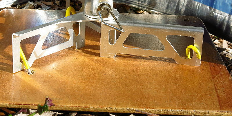
Stove stakes - to stop the stove from sliding around
A funny thing can happen when a stove gets really light. It can skitter around on the ground, which can be a shade disconcerting. It can also lurch as the legs move around on the ground and lose their support. One way to handle this is to use a solid stove base, and to put slight grooves in it to locate the legs. This works fine as long as the stove base doesn't slide away too easily. There's lots of scope for ingenuity here.
Another way which occurred to me is to 'anchor' the stove down. I made up a few tiny 'stove stakes' to test this idea. They worked beyond all expectation. Naturally, I used either 1 mm or 1.6 mm Ti wire. They weigh about 1 g each, with the yellow heat shrink on the end for visibility in the grass (I can not find dropped Ti stakes when they have no colour!). If you have a stove base underneath (eg light ply), some little holes in the right places are a good idea.
The next and final part in this series will stop waffling on about all the possibilities and focus on what was chosen and what it looks like. It's here.